Email: BuddyZhang1 buddy.zhang@aliyun.com
目录
SPI 原理
SPI 是英语 Serial Peripheral interface 的缩写,顾名思义就是串行外围设备接口, 是 Motorola 首先在其 MC68HCXX 系列处理器上定义的。SPI 接口主要应用在 EEPROM, FLASH,实时时钟,AD转换器,还有数字信号处理器和数字信号解码器之间。SPI 是一种 高速的,全双工,同步的通信总线,并且在芯片的管脚上只占用四根线,节约了芯片的管 脚,同时为 PCB 的布局上节省空间,提供方便。
+------------------------+                    +------------------------+
|                  SCLK -|------------------->|  SCLK                  |
|  SPI             MOSI -|------------------->|  MOSI             SPI  |
| Master           MISO  |<-------------------|- MISO            Slave |
|                  CS^  -|------------------->|  CS^                   |
+------------------------+                    +------------------------+
SPI 的通信原理很简单,它以主从方式工作,这种模式通常有一个主设备和一个或多个从 设备,需要 4 根线,事实上 3 根也可以。也是所有基于 SPI 的设备共有的,它们是 SDI (数据输入),SDO (数据输出),SCLK (时钟),CS (片选)
MOSI(SDO):主器件数据输出,从器件数据输入。
MISO(SDI):主器件数据输入,从器件数据输出。
SCLK :时钟信号,由主器件产生。
CS:从器件使能信号,由主器件控制。
其中 CS 是控制芯片是否被选中的,也就是说只有片选信号为预先规定的使能信号时(高 电位或低电位),对此芯片的操作才有效,这就允许在同一总线上连接多个 SPI 设备成 为可能。需要注意的是,在具体的应用中,当一条 SPI 总线上连接有多个设备时,SPI 本身的 CS 有可能被其他的 GPIO 脚代替,即每个设备的 CS 脚被连接到处理器端不同的 GPIO,通过操作不同的 GPIO 口来控制具体的需要操作的 SPI 设备,减少各个 SPI 设 备间的干扰。
SPI 协议
SPI 是串行通讯协议,也就是说数据是一位一位从 MSB 或者 LSB 开始传输的,这就是 SCK 时钟线存在的原因,由 SCK 提供时钟脉冲,MISO、MOSI 则基于此脉冲完成数据传 输。 SPI 支持 4-32bits 的串行数据传输,支持 MSB 和 LSB,每次数据传输时当从设 备的大小端发生变化时需要重新设置 SPI Master 的大小端。
SPI 时钟模式
SPI 总线有四种工作模式,其中使用的最为广泛的是 SPI0 和 SPI3 方式(实线表示)
四种工作方式时序分别为:
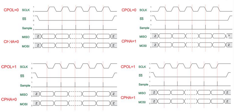
时序详解
- CPOL:时钟极性选择,为 0 时 SPI 总线空闲为低电平,为 1 时 SPI 总线空闲为 高电平
- CPHA:时钟相位选择,为 0 时在 SCK 第一个跳变沿采样,为 1 时在 SCK 第二个 跳变沿采样
工作方式 1
当 CPHA=0、CPOL=0 时SPI总线工作在方式1。MISO引脚上的数据在第一个SPSCK沿跳变之 前已经上线了,而为了保证正确传输,MOSI引脚的MSB位必须与SPSCK的第一个边沿同步, 在SPI传输过程中,首先将数据上线,然后在同步时钟信号的上升沿时,SPI的接收方捕捉 位信号,在时钟信号的一个周期结束时(下降沿),下一位数据信号上线,再重复上述过 程,直到一个字节的8位信号传输结束。
工作方式 2
当 CPHA=0、CPOL=1 时SPI总线工作在方式2。与前者唯一不同之处只是在同步时钟信号的 下降沿时捕捉位信号,上升沿时下一位数据上线。
工作方式 3
当 CPHA=1、CPOL=0 时 SPI 总线工作在方式3。MISO引脚和MOSI引脚上的数据的MSB位必 须与SPSCK的第一个边沿同步,在SPI传输过程中,在同步时钟信号周期开始时(上升沿) 数据上线,然后在同步时钟信号的下降沿时,SPI的接收方捕捉位信号,在时钟信号的一 个周期结束时(上升沿),下一位数据信号上线,再重复上述过程,直到一个字节的8位 信号传输结束。
工作方式 4
当CPHA=1、CPOL=1时SPI总线工作在方式4。与前者唯一不同之处只是在同步时钟信号的上 升沿时捕捉位信号,下降沿时下一位数据上线。
Uboot 中访问 SPI
开发者在 Uboot 阶段可以通过两种方式访问 SPI 从设备。分别是:
工具访问 SPI
在 Uboot 命令行模式下,系统提供了 sf 工具来操作 SPI-Flash。通过这个工具可以进 行 SPI-Flash 的读,写,擦除,和更新操作。工具的使用方法如下:
ZynqMP> sf
sf - SPI flash sub-system

Usage:
sf probe [[bus:]cs] [hz] [mode] - init flash device on given SPI bus
                                  and chip select
sf read addr offset|partition len       - read `len' bytes starting at
                                          `offset' or from start of mtd
                                          `partition'to memory at `addr'
sf write addr offset|partition len      - write `len' bytes from memory
                                          at `addr' to flash at `offset'
                                          or to start of mtd `partition'
sf erase offset|partition [+]len        - erase `len' bytes from `offset'
                                          or from start of mtd `partition'
                                         `+len' round up `len' to block size
sf update addr offset|partition len     - erase and write `len' bytes from memoy
                                          at `addr' to flash at `offset'
                                          or to start of mtd `partition'
sf protect lock/unlock sector len       - protect/unprotect 'len' bytes starting
                                          at address 'sector'

ZynqMP>
初始化 SPI-Flash
sf probe 命令用于初始化 SPI-Flash 控制器,使用模式如下:
sf probe [[bus:]cs] [hz] [mode]例如,探测并初始化系统可用的 SPI-Flash:
ZynqMP> sf probe
SF: Detected n25q256a with page size 512 Bytes, erase size 128 KiB, total 64 MiB
ZynqMP>
SPI-Flash 读
sf read 命令用于从 SPI-Flash 的特定位置上,读一定长度的数据到内存指定位置 上。使用格式如下:
sf read addr offset|partition len例如,从 SPI-Flash 0x100 的位置上,读取 0x2000 个字节到内存的 0x40000 位置上:
ZynqMP> sf read 0x40000 0x100 0x2000
device 0 offset 0x100, size 0x2000
SF: 8192 bytes @ 0x100 Read: OK
ZynqMP>
SPI-Flash 写
sf write 命令用于从内存指定位置,写一定长度的数据到 SPI-Flash 的指定位置 上,使用格式如下:
sf write addr offset|partition len例如,从内存 0x40000 处,写 0x10 字节到 SPI-Flash 0x3F00000 位置上:
ZynqMP> sf write 0x40000 0x3F00000 0x10
device 0 offset 0x3f00000, size 0x10
SF: 16 bytes @ 0x3f00000 Written: OK
ZynqMP>
SPI-Flash 擦除
sf erase 命令用于擦除 SPI-Flash 上一段内容,使用格式如下:
sf erase offset|partition [+]len例如,擦除 SPI-Flash 0x3F00000 开始处,长度为 0x100000 字节的数据
ZynqMP> sf erase 0x3f00000 0x100000
SF: 1048576 bytes @ 0x3f00000 Erased: OK
ZynqMP>
SPI-Fash 更新
sf update 命令用于更新 SPI-Flash 上指定区域内的数据,对比数据在内存的指定 位置上,使用模式如下:
sf update addr offset|partition len例如,将内核 0x400 处 0x10 个字节更新到 SPI-Flash 0x3F00000 开始的地址:
ZynqMP> sf update 0x4000 0x3F00000 0x10
device 0 offset 0x3f00000, size 0x10
16 bytes written, 0 bytes skipped in 0.41s, speed 372 B/s
ZynqMP>
源码访问 SPI
开发者也可以通过源码在 Uboot 中访问 SPI,可以参考如下代码:
/*
* SPI read/write on Uboot
*
* (C) 2018.11.18 BiscuitOS <buddy.zhang@aliyun.com>
*
* This program is free software; you can redistribute it and/or modify
* it under the terms of the GNU General Public License version 2 as
* published by the Free Software Foundation.
*/
#include <common.h>
#include <spi.h>

/* Init slave device */
struct spi_slave *spi_slave_init(void)
{
    struct spi_slave *slave;
    unsigned int bus = 0;
    unsigned int cs  = 2;
    unsigned int mode = SPI_MODE_0;

    slave = spi_setup_slave(bus, cs, 1000000, mode);
    if (!slave) {
        printf("Invalid device %d:%d\n", bus, cs);
        return NULL;
    }

    spi_claim_bus(slave);

    return slave;
}

/* SPI read/write operation */
static int spi_read_write(struct spi_slave *spi, const u8 *cmd,
                    size_t cmd_len, const u8 *data_out, size_t data_len)
{
    unsigned long flags = SPI_XFER_BEGIN;
    int ret;

    if (data_len == 0)
        flags |= SPI_XFER_END;

    ret = spi_xfer(spi, cmd_len * 8, cmd, NULL, flags);
    if (ret) {
        printf("Invalid send command\n");
    } else if (data_len != 0) {
        ret = spi_xfer(spi, data_len * 8, data_out, data_on, SPI_XFER_END);
        if (ret)
            printf("Incalid transfer data\n");
    }

    return ret;
}
Kernel 中访问 SPI
内核中要能访问 SPI,需要准备以下几个内容
SPI 设备驱动
SPI 设备驱动,开发者可以参考如下:
/*
* SPI read/write on Kernel
*
* (C) 2018.11.19 BuddyZhang1 <buddy.zhang@aliyun.com>
*
* This program is free software; you can redistribute it and/or modify
* it under the terms of the GNU General Public License version 2 as
* published by the Free Software Foundation.
*/
#include <linux/kernel.h>
#include <linux/init.h>
#include <linux/module.h>
#include <linux/spi/spi.h>
#include <linux/spi/spidev.h>
#include <linux/of.h>
#include <linux/of_device.h>

/*
* SPI device on DTS
*
* &spi0 {
*     status = "okay";
*
*     spi_demo@2 {
*         compatible = "spi_demo";
*         #address-cells = <1>;
*         #size-cells = <1>;
*         reg = <0x2>;
*         spi-max-frequency = <5000000>;
*     };
* };
*/

#define DEV_NAME                "spi_demo"
#define SPI_TRANSFER_BUF_LEN    14

/* SPI interface instruction set */
#define INSTRUCTION_WRITE       0x02
#define INSTRUCTION_READ        0x03
#define INSTRUCTION_BIT_MODIFY  0x05

struct spi_demo_priv {
    struct spi_device *spi;

    u8 *spi_tx_buf;
    u8 *spi_rx_buf;
};

static int spi_demo_trans(struct spi_device *spi, int len)
{
    struct spi_demo_priv *priv = spi_get_drvdata(spi);
    struct spi_transfer t = {
        .tx_buf = priv->spi_tx_buf,
        .rx_buf = priv->spi_rx_buf,
        .len    = len,
        .cs_change = 0,
    };
    struct spi_message msg;
    int ret;

    spi_message_init(&msg);

    spi_message_add_tail(&t, &msg);

    ret = spi_sync(spi, &msg);
    if (ret)
        printk(KERN_ERR "spi transfer failed, ret = %d\n", ret);
    return ret;
}

/*
* Read one byte from SPI slave device
*  @spi: spi slave device
*  @reg: register need to read.
*
* if succeed, return the value of register.
*/
static u8 spi_demo_read_reg(struct spi_device *spi, uint8_t reg)
{
    struct spi_demo_priv *priv = spi_get_drvdata(spi);
    u8 val = 0;

    priv->spi_tx_buf[0] = INSTRUCTION_READ;
    priv->spi_tx_buf[1] = reg;

    spi_demo_trans(spi, 3);
    val = priv->spi_rx_buf[2];

    return val;
}

/*
* Read two byte from SPI slave device
*  @spi: SPi slave device.
*  @reg: register need to read.
*
* if succeed, v1 is first registe's value and v2 is second register's value.
*/
static void spi_demo_read_2regs(struct spi_device *spi, uint8_t reg,
                            uint8_t *v1, uint8_t *v2)
{
    struct spi_demo_priv *priv = spi_get_drvdata(spi);

    priv->spi_tx_buf[0] = INSTRUCTION_READ;
    priv->spi_tx_buf[1] = reg;

    spi_demo_trans(spi, 4);

    *v1 = priv->spi_rx_buf[2];
    *v2 = priv->spi_rx_buf[3];
}

/*
* Write one byte to SPI slave device
*  @spi: SPI slave device
*  @reg: Regsiter need to write
*  @val: data need to write.
*/
static void spi_demo_write_reg(struct spi_device *spi, u8 reg, uint8_t val)
{
    struct spi_demo_priv *priv = spi_get_drvdata(spi);

    priv->spi_tx_buf[0] = INSTRUCTION_WRITE;
    priv->spi_tx_buf[1] = reg;
    priv->spi_tx_buf[2] = val;

    spi_demo_trans(spi, 3);
}

/*
* Change speical bit on SPI slave device.
*  @spi: SPI slave device.
*  @reg: register need to write.
*  @mask: mask for modify.
*  @val: data need to write.
*/
static void spi_demo_write_bits(struct spi_device *spi, u8 reg,
                                   u8 mask, uint8_t val)
{
    struct spi_demo_priv *priv = spi_get_drvdata(spi);

    priv->spi_tx_buf[0] = INSTRUCTION_BIT_MODIFY;
    priv->spi_tx_buf[1] = reg;
    priv->spi_tx_buf[2] = mask;
    priv->spi_tx_buf[3] = val;

    spi_demo_trans(spi, 4);
}

/*
* SPI Slave device probe entence
*/
static int spi_demo_probe(struct spi_device *spi)
{
    struct spi_demo_priv priv;
    int value;

    spi_set_drvdata(spi, &priv);

    /* Configure the SPI bus */
    spi->bits_per_word = 8;
    spi->max_speed_hz = spi->max_speed_hz ? : 10 * 1000 * 1000;

    /* Power up SPI slave device */

    spi_setup(spi);

    /* Allocate non-DMA buffers */
    priv.spi_tx_buf = devm_kzalloc(&spi->dev, SPI_TRANSFER_BUF_LEN,
                                          GFP_KERNEL);
    priv.spi_rx_buf = devm_kzalloc(&spi->dev, SPI_TRANSFER_BUF_LEN,
                                          GFP_KERNEL);

    /* Read data from SPI slave device */
    value = spi_demo_read_reg(spi, 0x10);

    /* Write data into SPI slave device */
    spi_demo_write_reg(spi, 0x10, value);

    return 0;
}

/*
* SPI Slave device remove entence
*/
static int spi_demo_remove(struct spi_device *spi)
{
    /* Power off SPI slave device */

    return 0;
}

static const struct of_device_id spi_demo_dt_ids[] = {
    { .compatible = DEV_NAME },
    { },
};

static const struct spi_device_id spi_demo_id[] = {
    { DEV_NAME },
    { }
};

MODULE_DEVICE_TABLE(spi, spi_demo_id);

static struct spi_driver spi_demo_driver = {
    .driver = {
        .name  = DEV_NAME,
        .owner = THIS_MODULE,
        .of_match_table = of_match_ptr(spi_demo_dt_ids),
    },
    .probe    = spi_demo_probe,
    .remove   = spi_demo_remove,
    .id_table = spi_demo_id,
};

module_spi_driver(spi_demo_driver);

MODULE_LICENSE("GPL v2");
MODULE_ALIAS("spi demo");
Makefile
obj-m += spi.o

KERNELDIR ?= /lib/modules/$(shell uname -r)/build

PWD       := $(shell pwd)

ROOT := $(dir $(M))
DEMOINCLUDE := -I$(ROOT)../include -I$(ROOT)/include

GCCVERSION = $(shell gcc -dumpversion | sed -e 's/\.\([0-9][0-9]\)/\1/g' -e 's/\.\([0-9]\)/0\1/g' -e 's/^[0-9]\{3,4\}$$/&00/')

GCC49 := $(shell expr $(GCCVERSION) \>= 40900)

all:
        $(MAKE) -C $(KERNELDIR) M=$(PWD) modules

install: all
        $(MAKE) -C $(KERNELDIR) M=$(PWD) modules_install
        depmod -a

clean:
        rm -rf *.o *.o.d *~ core .depend .*.cmd *.ko *.ko.unsigned *.mod.c .tmp_versions *.symvers \
        .cache.mk *.save *.bak Modules.* modules.order Module.markers *.bin

CFLAGS_spi.o := -Wall $(DEMOINCLUDE)

ifeq ($(GCC49),1)
        CFLAGS_spi.o += -Wno-error=date-time
endif

CFLAGS_spi.o := $(DEMOINCLUDE)
SPI 驱动可以加载到内核也可以外部编译,编译命令如下:
make clean
make
sudo insmod spi.ko
SPI 设备在 DTS 中的描述
准备好驱动之后,接下来需要在 DTS 中添加 SPI 设备的描述。开发者可以参考如下:
&spi0 {
    status = "okay";

    spi_demo@2 {
        compatible = "spi_demo";
        #address-cells = <1>;
        #size-cells = <1>;
        reg = <0x2>;
        spi-max-frequency = <5000000>;
    };
};
SPI 相关的宏
为了能在系统中运行 SPI 设备驱动,请确保内核已经打开如下宏:
CONFIG_SPI=y
CONFIG_SPI_MASTER=y
CONFIG_SPI_ORION=y
用户空间访问 SPI
用户空间也可以通过两种方式访问 SPI,分别如下:
使用工具访问 SPI
Linux 用户空间有多种 SPI 工具,这里介绍 spi-tools, 这个工具可以通过 busybox 提 供或直接源码编译使用。具体使用步骤如下:
git clone https://github.com/msperl/spi-config.git
cd spi-config/
make
make install
使用格式:
modprobe spi-config devices=<devicedev1>,<devicedev2>,...,<devicedev16>例如:
modprobe spi-config devices=\
bus=0:cs=0:modalias=mcp2515:speed=10000000:gpioirq=25:pd=20:pdu32-0=16000000:pdu32-4=0x2002,\
bus=0:cs=1:modalias=mcp2515:speed=6000000:gpioirq=22:pd=0x14:pdu32-0=20000000:pdu32-4=0x02
详细步骤,请查看 github:
https://github.com/BiscuitOS/HardStack/blob/master/bus/spi/user/README.md
源码访问 SPI
通过源码在用户空间访问 SPI,开发者可以参考如下代码:
/*
* SPI testing utility (using spidev driver)
*
* Copyright (c) 2007  MontaVista Software, Inc.
* Copyright (c) 2007  Anton Vorontsov
*
* This program is free software; you can redistribute it and/or modify
* it under the terms of the GNU General Public License as published by
* the Free Software Foundation; either version 2 of the License.
*
* Cross-compile with cross-gcc -I/path/to/cross-kernel/include
*
*/
#include <stdint.h>
#include <unistd.h>
#include <stdio.h>
#include <stdlib.h>
#include <getopt.h>
#include <fcntl.h>
#include <sys/ioctl.h>
#include <linux/types.h>
#include <linux/spi/spidev.h>

#define ARRAY_SIZE(a) (sizeof(a) / sizeof((a)[0]))

static void pabort(const char *s)
{
    perror(s);
    abort();
}

static const char *device = "/dev/spidev1.1";
static uint8_t mode = 3;
static uint8_t bits = 8;
static uint32_t speed = 1000000;
static uint16_t delay;

static void transfer(int fd)
{
    int ret;
    uint8_t tx[] = {
                0xFF, 0xFF, 0xFF, 0xFF, 0xFF, 0xFF,
                0x40, 0x00, 0x00, 0x00, 0x00, 0x95,
                0xFF, 0xFF, 0xFF, 0xFF, 0xFF, 0xFF,
                0xFF, 0xFF, 0xFF, 0xFF, 0xFF, 0xFF,
                0xFF, 0xFF, 0xFF, 0xFF, 0xFF, 0xFF,
                0xDE, 0xAD, 0xBE, 0xEF, 0xBA, 0xAD,
                0xF0, 0x0D,
    };
    uint8_t rx[ARRAY_SIZE(tx)] = {0, };
    struct spi_ioc_transfer tr = {
        .tx_buf = (unsigned long)tx,
        .rx_buf = (unsigned long)rx,
        .len = ARRAY_SIZE(tx),
        .delay_usecs = delay,
        .speed_hz = 0,
        .bits_per_word = 0,
    };

    ret = ioctl(fd, SPI_IOC_MESSAGE(1), &tr);
    if (ret == 1)
        pabort("can't send spi message");

    for (ret = 0; ret < ARRAY_SIZE(tx); ret++) {
        if (!(ret % 6))
            puts("");
        printf("%.2X ", rx[ret]);
    }
    puts("");
}

void print_usage(const char *prog)
{
    printf("Usage: %s [-DsbdlHOLC3]\n", prog);
    puts("  -D --device   device to use (default /dev/spidev1.1)\n"
         "  -s --speed    max speed (Hz)\n"
         "  -d --delay    delay (usec)\n"
         "  -b --bpw      bits per word \n"
         "  -l --loop     loopback\n"
         "  -H --cpha     clock phase\n"
         "  -O --cpol     clock polarity\n"
         "  -L --lsb      least significant bit first\n"
         "  -C --cs-high  chip select active high\n"
         "  -3 --3wire    SI/SO signals shared\n");
    exit(1);
}

void parse_opts(int argc, char *argv[])
{
    while (1) {
        static const struct option lopts[] = {
            { "device",  1, 0, 'D' },
            { "speed",   1, 0, 's' },
            { "delay",   1, 0, 'd' },
            { "bpw",     1, 0, 'b' },
            { "loop",    0, 0, 'l' },
            { "cpha",    0, 0, 'H' },
            { "cpol",    0, 0, 'O' },
            { "lsb",     0, 0, 'L' },
            { "cs-high", 0, 0, 'C' },
            { "3wire",   0, 0, '3' },
            { NULL, 0, 0, 0 },
        };
        int c;

        c = getopt_long(argc, argv, "D:s:d:b:lHOLC3", lopts, NULL);
        if (c == -1)
            break;
        switch (c) {
        case 'D':
            device = optarg;
            break;
        case 's':
            speed = atoi(optarg);
            break;
        case 'd':
            delay = atoi(optarg);
            break;
        case 'b':
            bits = atoi(optarg);
            break;
        case 'l':
            mode |= SPI_LOOP;
            break;
        case 'H':
            mode |= SPI_CPHA;
            break;
        case 'O':
            mode |= SPI_CPOL;
            break;
        case 'L':
            mode |= SPI_LSB_FIRST;
            break;
        case 'C':
            mode |= SPI_CS_HIGH;
            break;
        case '3':
            mode |= SPI_3WIRE;
            break;
        default:
            print_usage(argv[0]);
            break;
        }
    }
}

int main(int argc, char *argv[])
{
    int ret = 0;
    int fd;

    parse_opts(argc, argv);
    fd = open(device, O_RDWR);
    if (fd < 0)
        pabort("can't open device");

    /* spi mode */
    ret = ioctl(fd, SPI_IOC_WR_MODE, &mode);
    if (ret == -1)
        pabort("can't set spi mode");

    ret = ioctl(fd, SPI_IOC_RD_MODE, &mode);
    if (ret == -1)
        pabort("can't get spi mode");

    /* bits per word */
    ret = ioctl(fd, SPI_IOC_WR_BITS_PER_WORD, &bits);
    if (ret == -1)
        pabort("can't set bits per word");

    ret = ioctl(fd, SPI_IOC_RD_BITS_PER_WORD, &bits);
    if (ret == -1)
        pabort("can't get bits per word");

    /* max speed hz */
    ret = ioctl(fd, SPI_IOC_WR_MAX_SPEED_HZ, &speed);
    if (ret == -1)
        pabort("can't set max speed hz");

    ret = ioctl(fd, SPI_IOC_RD_MAX_SPEED_HZ, &speed);
    if (ret == -1)
        pabort("can't get max speed hz");

    printf("spi mode: %d\n", mode);
    printf("bits per word: %d\n", bits);
    printf("max speed: %d Hz (%d KHz)\n", speed, speed/1000);

    transfer(fd);

    close(fd);

    return ret;
}
SPI 硬件波形测试
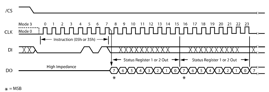
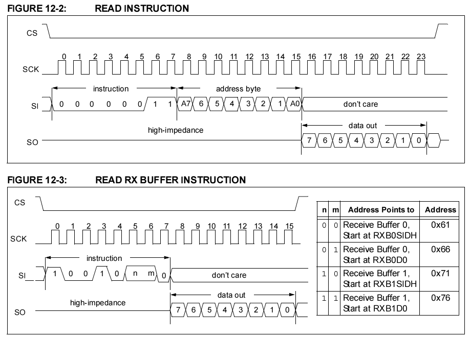
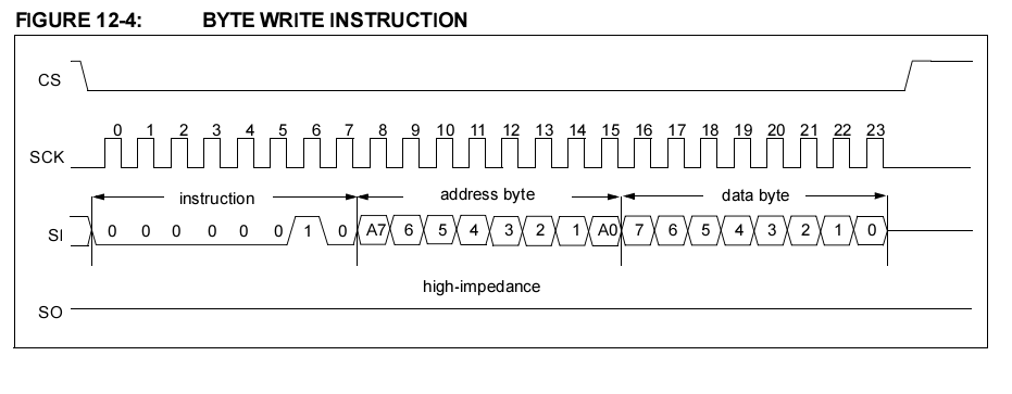
SPI 读写协议
SPI 读波形图
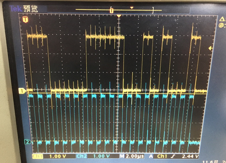
SPI 读实测波形图
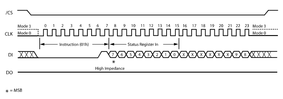
SPI 写波形图
SPI 实际测试波形图

附录
赞赏一下吧 🙂